Marisol Wickham Digital Portfolio
View the Project on GitHub 26wickhm/Wickham-Marisol-portfolio
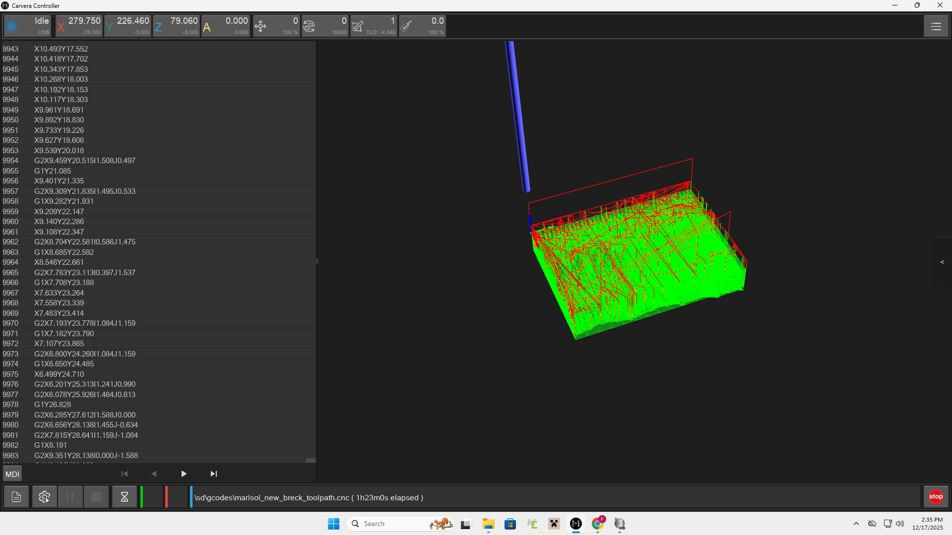
Topography Map of Breckendridge, Colorado
.jpg) |
.jpg) |
.jpg) |
.jpg) |
For this project, we utilized the MakeraCam machine to engrave topography maps into wood. I chose to do Breckendridge, Colorado.
FILES
This workflow is inspired by one that Tom Dubick created
Workflow
Terrain2STL (https://jthatch.com/Terrain2STL/)
- Find location and define model area by creating a red box around the georgraphy wanted
- Adjust water drop and base height (default of 1 to start)
- Generate model to download stl as a zip file
Aspire
- Open Aspire and create new file
- Job type: single side
- Width (x): 2.5 inches
- Height (y): 3.5 inches
- Thickness (z): 1.0 inch
- Z Zero Position: Material surface (top)
- XY Datum Position: Bottom left
- Model Resolution: Standard
- Click “OK”
- Import 3D Model
- Go to the modeling tab
- Click “Import a Component or 3D Model” and select your STL file
- Orient 3D Model (Imported 3D Model > Transform)
- Rotation abouty Z axis: 0 degrees
- Unclick “lock XYZ ratio”
- z = 1, x = 2.5, y = 3.5
- Click apply and center model
- Leave “Apply Perspective Along Z” unchecked
- Position and Import
- Use Depth Below to ensure that it is equal to the Z’s height size
- click import while on Position Relative to the Modeling Plane
- On the Component tab –> Component Properties
- Shape Height: 1.0
- Base Height: 0.25
- “Close”
- Design tab –> 2D view
- click “Center” under the Alignment Tool
- Design tab –> Create Vectors
- Draw rectangle around design (in this case, x = 2.5, y = 3.5) need to do this to trim around the final product
- Toolpaths Tab
- In the 2D view, click on the 3D model image
- Click 3D roughing toolpath
- Material: Hardwood
- Tool: Large 25 mm End Flute Mill (Also known as a 1/8 End Mill)
- Machine Limit Boundaries: Selected Vectors
- Machining Allowance: 0.024
- Strategy: 3D Raster
- Name the Toolpath –> Calculate - 3D Finishing Toolpath
- Material: Hardwood
- Tool: 1/8 Ball Nose
- Machine Limit Boundaries: Selected Vectors
- Strategy: Raster, with a 0 degree input
- Name the Toolpath –> Calculate - 2D Profile Toolpath Generation
- Boundary: Select the rectangular boundary
- Toolpath: 2D Roughing Toolpath
- Start Depth: 0
- Cut Depth: 0.5
- Material: Hardwood
- Tool: 1/8 End Mill
- Machine Vectors: Select “On” and Direction “Climb”
- Seperate Last Pass: leave unchecked
- Name the Toolpath –> Calculate
- Preview all Toolpaths
- save the G-code by clicking the Save Toolpath button
- Machine: Carvera Desktop CNC machine #### MakeraCam
- After saving the toolpath to the Drive, download and import in on the PC next to the MakeraCam Machine
- Upload the gcode after uploading the file
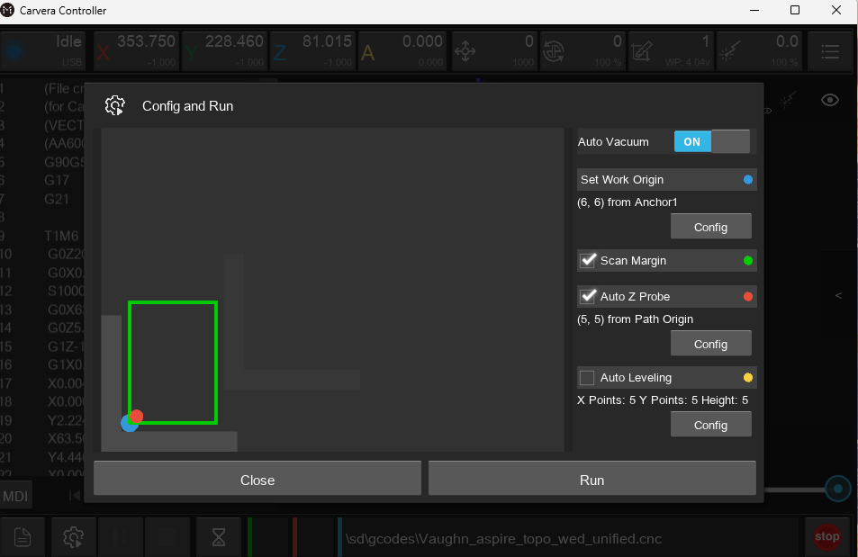
- Offset (6,6) to allow for the wood to be cut in the middle
- Run the gcode
CHALLENGES
A struggle that I encountered was with the exportation of the Aspire files and loading them onto the machine. This was because I continued to export the gcodes and the file would be empty when I moved to the PC connected to the MakeraCam. This was because I was not exporting it as a cnc. I had tried multiple times as a .nc, but once I saved it as a .cnc, it uploaded very easily and all I had to do was home and offset the machine.
SUMMARY
I think that the most important thing that I learned during this project is how to create the toolpath and navigate Aspire. I had to restart multiple times because of confusion, so I learned the process well and could do it without a workflow. If I were to change something, I think that I would make my zone more focused on the mountain range, and create more of a difference in the height. This would have added to the steepness of the mountain and pointed out each individual peak. In the future, I plan to stain this wood and mount it atop mulitple pieces of 1/8 inch wood. They will create a base slightly larger than the mountain. I will then engrave Breckenridge, Colorado on it and gift it to my parents.