Marisol Wickham Digital Portfolio
View the Project on GitHub 26wickhm/Wickham-Marisol-portfolio
MakeraCAM
Table of Contents
- Overview
- Learning the Software
- Files
- Milling the Board
- Notes & Takeaways
- Important Decisions
- Workflow
- Documentation from this work
- Summary
Overview
We started using MakeraCAM with our new CNC machine that has an auto tool-changer. This makes milling way faster and easier since it switches tools automatically — so you can start a job and work on something else while it runs.
Learning the Software
We learned how to:
- Import files and center them using coordinates (like
(6,6)for alignment) - Create pockets, contours, and drilling paths
- Assign tools and set up tool changes
- Export and run the g-code on the CNC
Files
Open Resistance1-Edge_Cuts.gbr
This file contains the gcode that I sent to the CNC machine
ResistorGcode.nc
Toolpath Creation Progression
| Before Toolpath | Pocketing | Drilling |
|---|---|---|
 |
 |
 |
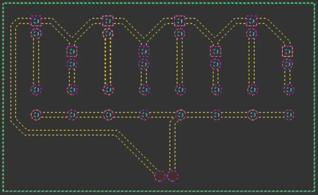
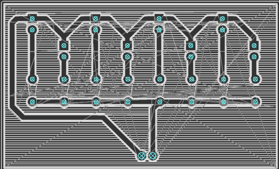
Below is what the toolpath looks like in MakeraCAM before milling:
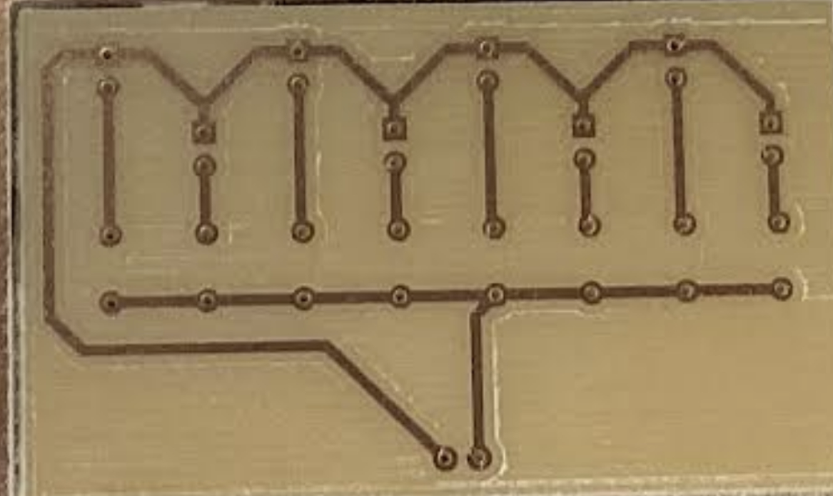
Milling the Board
After setting up the design, we placed the copper board on the CNC bed and ran the job. It milled all the traces and drilled the holes automatically.
Notes & Takeaways
- The auto tool-changer saves a lot of time
- The traces came out clean and sharp
- We learned how to adjust feed rates, depth, and pocketing for different materials
Challenges
- A challenge that I had was in the software while learning when to select which groups of lines for each direction
- I overcame this by following the workflow carefully and realizing when to restart
- There were no big challenges while milling and my PCB board came out well the first time
- It did take me a few tries to learn how to run the software and set up the board (which screws to unscrew)
Important Decisions
- I followed the workflow very carefully to ensure that I did not miss a step (this allowed me to follow a checklist and work efficiently so that I did not need to backtrack).
- I worked with a partner while running it (this allowed me to have help on my first time and then repeat it again with her, giving me practice and experience with the machine)
- I redid the toolpath by myself after we ran through it with Mr. Dubick to make sure that I knew how to select different sections and pick whether to pocket or drill.
Workflow
Preparing Design
Open new 3D project
- Set material to PCB: Edit → Material → PCB
- Set dimensions:
- X = 127 mm
- Y = 101 mm
- Z = 1.7 mm
Download files from Fab drive (blue folder named Dubick):
Resistance1-F_Cu.gbrResistance1-PTH.drlResistance1-Edge_Cuts.gbr
Import each file into MakeraCAM:
File → Import PCB → Downloads → Resistance1-Edge_Cuts.gbr → OpenFile → Import PCB → Downloads → Resistance1-PTH.drl → OpenFile → Import PCB → Downloads → Resistance1-F_Cu.gbr → Open
Anchor Lower Left Corner
- Select whole design
- Press “m”
- In the pop-up:
- Select the lower-left corner anchor (diagram on top right)
- Under Location, set coordinates to (6, 6)
Path Setup
Pocketing
- In 2D Layers, hide:
Resistance1-F_Cu.gbr_padResistance1-PTH.drl_0.900 mmResistance1-PTH.drl_1.400 mm
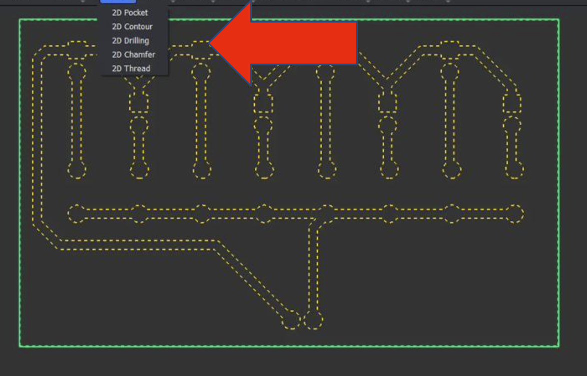
- Select: 2D Path → 2D Pocket
- Select whole visible design
- Set End Depth = 0.05 mm
- Add tools:
- 8mm Corn
- 0.2mm 30° Engraving (Metal)
- Click Calculate
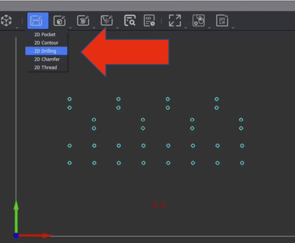
Drilling Holes
- 2D Path → 2D Drilling
- In 2D Layers, hide everything except the drilling file
- Set End Depth = 1.7 mm
- Add tool: 8mm Corn
- Click Calculate
Outside Cut
- 2D Path → 2D Contour
- In 2D Layers, hide everything except:
Resistance1-Edge_Cuts.gbr
- Set:
- End Depth = 1.7 mm
- Strategy: Outside
- Tabs:
- Tabs: Custom
- Tab Shape: Triangle
- Click Add
- Click 3 spots on the outer edge (evenly spaced)
- Add tool: 8mm Corn
- Click Calculate
Export Path
Path → Export → Export
Upload the exported file into your folder in the Fab Google Drive.
Milling Design
Installing Material
- Slightly loosen all bolts in the machine bed except the 3 fully inside the jig
- If a copper board is already on the bed:
- Remove and reorient if possible
- Otherwise replace with a new board
- Orient the PCB so the design will appear in the bottom-left corner
- Adjust the rectangular metal holders (slide/rotate without removing bolts)
- Slide PCB under loosened bolts
- Rotate holders so the slotted short edge presses the PCB down
- Tighten all bolts firmly (not overly tight)
Running the File
- Download your
gcode.ncfile from Fab Google Drive - Open Cavera Controller
- Upload File:
- Top left → Upload File
- Select your
.ncfile → Upload & Select
- Connect:
- Idle (top left) → COM Port ___
- Additional settings (top right):
- Display Manual Controls
- Home
- In Status:
- Ensure Voltage > 3.6V
- At the bottom bar → enable:
- Auto Vacuum
- Auto-Levelling
- Select Run
The machine will probe 25 points on the PCB, then begin milling.
Documentation from this work
(full documentation can be found by clicking on “Documentation” on the Home Page)
These journals are from the two days that I dedicated to MakeraCam. The first day follows my learning process on a moniter and the second day tracks my actual use of the machine.
10/27/25 Today we learned about a new software called MakeraCAM. I have never worked on this before, and at first it was very complicated. We pulled 3 files from the main drive (FabLab Drive under Dubick folder) so that we could focus on how to specify it instead of the actual design right now. I learned how to center the design (using coordinates (6, 6) and making a pocket, contour, and drilling. I also learned how to add specific tools depending on what kind of cuts I want the machine to make. This was helpful because I was able to learn new software (which will come in handy now that we have a new CNC machine). The benefits of this machine is that it switches out the tools unlike the manual version. This means that we can walk away after getting the g-code started, which leads to more efficiency in the lab.
10/31/25 Today I used our new CNC machine to mill a board. This was from a design that I made on Makera (the files were precreated but I had to specify the design depth, where to pocket, contour, and drill). This involved following a workflow created by a classmate that I altered to make more sense to me personally. This made the slightly complicated setup much easier to follow and check. I spent the other half of class (after I started running the program) on Github and updating my documentation and digital portfolio.
Summary
I think that this project was a good way to focus on creating and sending the gcode to the MakeraCam without getting caught up in the design. I realized how much a workflow can help during this assignment and feel confident in my ability to set up and run the new CNC machine. This is also very interesting because it is much more cost efficient and helpful for the electronic part of my Capstone Peoject (depending on which Pearl projects require it). I plan to get more comfortable with it during my mountain range project and want to learn how to use the CNC machine on different materials with different tools.